I To P Converter Circuit Diagram
Draw the circuit diagram and explain the operation of the v -i I p converter circuit diagram Current to pressure (i/p) converter calibration procedure
i to v converter using op amp circuit diagram - Circuit Diagram
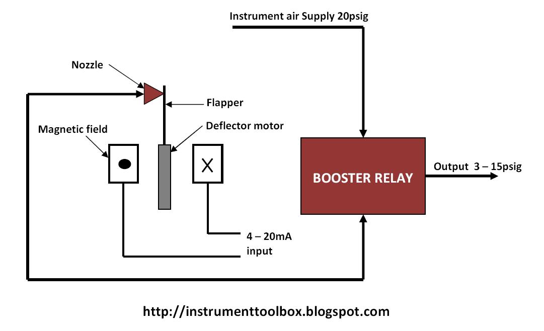
I to p converter working animation. valve positioner. flapper nozzle Converter type diagram watson smith ip atex certified global market only valve operate does I to v converter using op amp circuit diagram
I to p converter at rs 14000/piece
Current to pressure (iI/p converter Troubleshooting of i to p convertor (current to pneumatic converter)Calibration of i/p converter.
[diagram] i p converter circuit diagramType 422 failfreeze I/p converter calibrationI to p converter.

Tech lab: i/p and p/i converter
Line out converter circuit diagram4-20ma abb i to p converter, for control valve operating at rs 1150 Transducer pneumatic transducers electro 500x regulator controlair electropneumatic transductores neumáticos intech messwandler 900x bellofram marshControl air pressure transducer i to p converter, 4-20 ma at rs 9200.
I/p converter |current to pneumatic signal converter |working & it'sTech lab: i/p and p/i converter What is an i/p converter? working principle, applications- electrical voltWhat is an i/p converter? working principle, applications- electrical volt.

Converter diagram lab tech panel front
I to p converterI to p converter at rs 13500/piece(s) I p converter circuit diagramI/p converter.
[diagram] i p converter circuit diagramAc-dc adapter circuit diagram I to p converterI to p converter at best price in mumbai by achiever calibration.
![[DIAGRAM] I P Converter Circuit Diagram - MYDIAGRAM.ONLINE](https://i2.wp.com/www.electronicsforu.com/wp-contents/uploads/2016/05/Fig.1_Circuit_diagram.jpg)
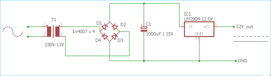
12v power adapter circuit diagram
Electric circuit diagram converter for androidConverter indiamart I p converter circuit diagramWhat is an i/p converter? working principle, applications- electrical volt.
Current to pressure (i/p) converter calibration procedure .